vacuum tube plasma generator (HFVTTC)
This is a loosely connected set of notes regarding my vacuum tube driven plasma generator showcased in this video.
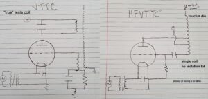
There does not seem to be a consensus on naming of this circuit in English, but some common names include vacuum tube plasma generator, RF torch, torch discharge, high frequency vacuum tube tesla coil (HFVTTC), base fed Tesla coil, and other names as well. Unfortunately, some of these names aren’t very accurate and there are other types of circuits that can share the same name.
you’d probably die if you attempted anything on this page or website so please don’t try this at home
BUILD NOTES
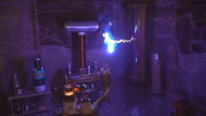
There is very little info on this circuit online, especially at higher powers. This is due to a few reasons. For one, the circuit is EXTREMELY dangerous. It is MUCH more dangerous than a classic vacuum tube Tesla coil (VTTC) since the output is directly connected to the lethal HV power supply.
It is also a major fire hazard and can melt nearly anything placed on the output. If not properly operated, the circuit can be a major source of EMI that can destroy nearby electronics or cause illegal interference. The circuit can also be very chaotic and unpredictable. Finally, what little info you can find is almost always in the Russian language. It turns out the first person to write about the circuit’s effects was the soviet scientist S. I. Zilitinkevich way back in 1928(!!) but there are only sparse English translations of the following literature.
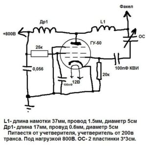
I can’t remember the first time I learned about the circuit, but it was probably somewhere on the 4HV forums. Most of the HFVTTC builds I’ve seen use the following schematic. I’m not sure where it came from, but it is the first Google result for “HFVTTC schematic”.
I wanted something much stronger, and preferred using the powerful soviet GU-5B triode that I already had on hand. I could only find two other people that had built an HFVTTC with this tube, and these people are Teslista555 on YouTube (his build notes here) and Zilipoper on YouTube . Their builds were an excellent reference for getting my circuit at least to the point of flame breakout. Everything else from then on was all trial and error. At the point I stopped filming, this is what my schematic looked like:
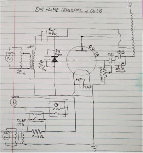
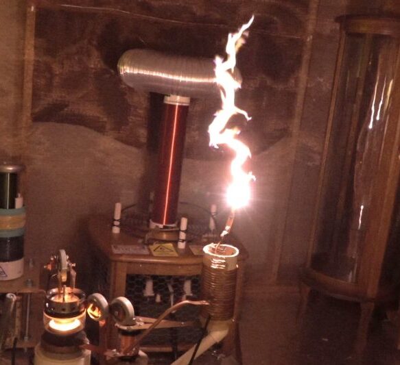
It’s a simple schematic actually, where the real art is in how you make the connections (as those add stray inductance, capacitance, etc. that change fundamental values of the circuit.) The vacuum variable capacitor can be omitted, as at this point the changes it makes are fairly trivial. All capacitors other than the main doubler caps are all soviet RF doorknob capacitors. The output coil is 20 turns, tapped at turn 0, 2.5, and 11, wound with 1/8″ diameter copper pipe on 3″ diameter cardboard tubing. The relay circuit at the bottoms is just a soft start for the filament, and of course there are some fans thrown in there to cool the tube.
EXPERIMENTS AND OPERATION
This circuit is incredibly chaotic but also tough as nails. It is self tuned, which makes it quite tolerant to dynamic loads (aka burning objects) on the output. It is impossible to run without a variac. I have (analog) meters reading the anode voltage and grid current, as well as a power meter on the input of my variac to make sure I keep the tube somewhat close to its rated values.
yeeting a zinc electrode on the HFVTTC
The power draw is highly dependent on the output electrode. Swapping out electrodes can cause a more than double increase in the power draw for a given input voltage!
[more coming soon]
video: